Mastering Data Acquisition with Arduino
As part of a larger project, I needed to gather some data remotely. In my case it was accelerometer and frequency data from a reed switch. Either way, I needed a robust way to log data from a variety of sensors onto a memory card of some kind remotely. I decided that the simplest way was probably with Arduino, and quickly hacked together something that worked well enough on a breadboard, then took things a little far and started using the opportunity to learn to use EagleCAD.
The first shield I designed and had made was pretty ridiculously simple. Mostly it was an experience in learning to select my components, draw the schematic, space everything out right, and draw traces. I did a good bit wrong, it took embarrassingly long, but I ended up with something that resembled a circuit board.
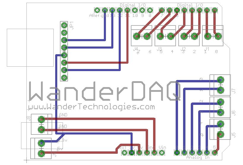
Thrilled with my apparent success, I converted everything to Gerber files and ordered some prototypes. When they showed up, they looked beautiful. It’s so cool to design something and then hold it in your hands.
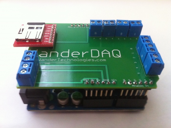
Unfortunately they didn’t work, and I had no idea why, so I spent days troubleshooting whatever I could find. One mis-routed trace was easily enough fixed with a blue wire, but still no dice. Plus the terminals were spaced completely wrong. Incredibly frustrated, I started over.
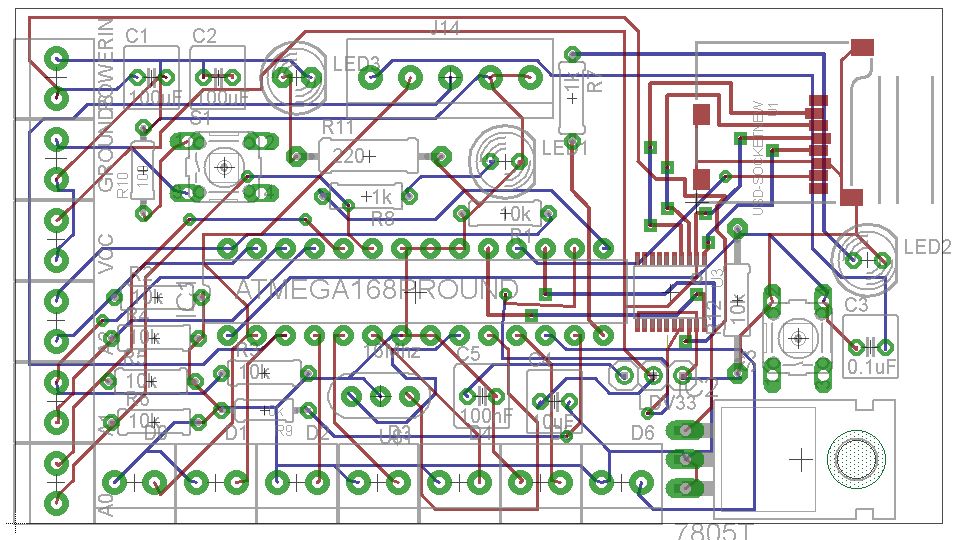
The next revision included a lot more, pull down resistors on the analog pins, a button, and 2 LEDs. The hope was that I had just overheated the microSD breakout boards when soldering them to the first set of boards, so I kind of just crossed my fingers and used headers to make the SD boards removable.
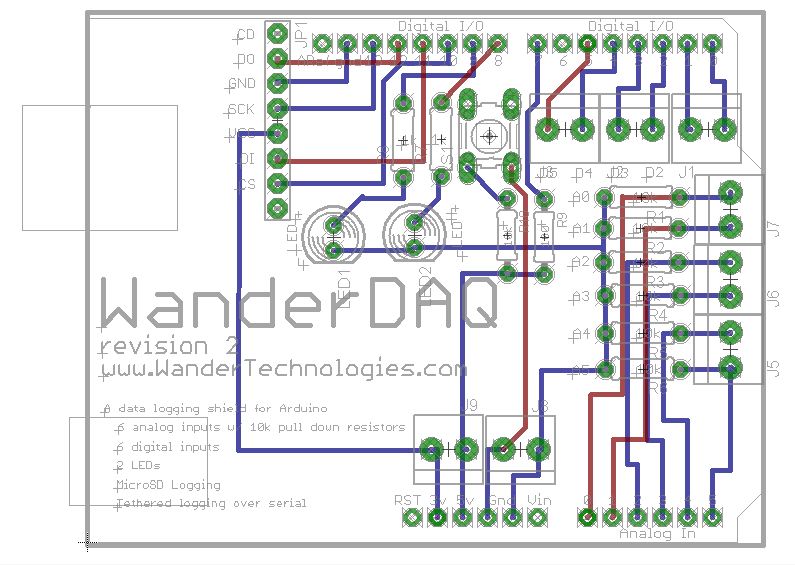
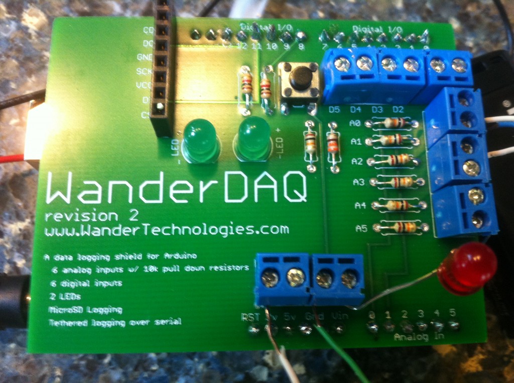
While the revised boards were in transit though, I realized my stupid mistake. The microSD cards don’t just need 3.3v power, they also need 3.3v logic. The Arduino Uno board has 5v logic. Frustrated, I ordered a 3.3v Arduino Pro, to test out my theory, and sure enough, when the new board and new shield were plugged together, perfect, seamless logging.
Terminals are still messed up.
With this new revelation, I set out to design a board that will actually convert the 5v logic to 3.3v so the board can be used with the much more common 5v Arduinos. Here is the design so far, with the final order waiting on some breadboard testing of the logic level converter chip.
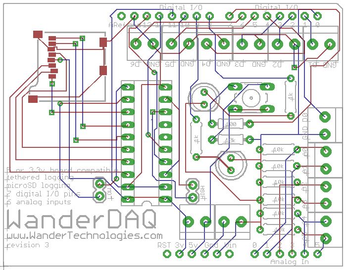
And maybe down the road, a standalone Arduino compatible board that does it all.
More detail was available on the WanderDAQ project page, but that site is no longer maintained. The key learning from this project was about the importance of voltage level conversion when working with mixed voltage systems - a lesson I’ve carried forward into many other projects.
Stay in the loop
Get notified when I publish new posts. No spam, unsubscribe anytime.